1 Introduction
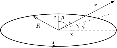
In this document we present the magnetic properties of current loops. To obtain a good understanding of the basic physical properties, we analyze in detail the properties of a ring made of an infinitesimally thin ideal conductor, carrying an homogeneous current \(I\) (see Fig. 1).
2 Electromagnetic Fields
The magnetic induction \(\mathbf{B}\) generated by a current loop is most conveniently calculated from the vector potential \(\mathbf{A}\). The vector potential of a known current distribution can be calculated directly from the general solution of Maxwell’s equations [1]: \[\begin{equation} \label{eq:vec_pot_gen_sol} \underline{\mathbf{A}}(\mathbf{r}) = \frac{\mu}{4\pi} \int\!\!\!\int\!\!\!\int_{V^{'}} \frac{\underline{\mathbf{J}}(\mathbf{r}^{'})\cdot e^{-j k|\mathbf{r} - \mathbf{r}^{'}|}} {|\mathbf{r} - \mathbf{r}^{'}|}\, \dd V^{'} \end{equation}\] with \(\underline{\mathbf{J}}\) the phasor of the current density, and \(V^{'}\) the volume over which the current density is non zero. The magnetic induction \(\underline{\mathbf{B}}\) is then \[\underline{\mathbf{B}}(\mathbf{r}) = \nabla\times\underline{\mathbf{A}} = \frac{\mu}{4\pi} \int\!\!\!\int\!\!\!\int_{V^{'}} \nabla\times \frac{\underline{\mathbf{J}}(\mathbf{r}^{'})\cdot e^{-j k|\mathbf{r} - \mathbf{r}^{'}|}} {|\mathbf{r} - \mathbf{r}^{'}|}\, \dd V^{'}\] where we have exchanged differentiation and integration order.
In the case of a very thin homogeneous current distribution, as it is assumed here, the threefold integral can be reduced to a simple path integral along the current path \(\Gamma\) \[\underline{\mathbf{B}}(\mathbf{r}) = \frac{\mu \underline{I}_0}{4\pi} \oint_{\Gamma} \nabla\times \frac{e^{-j k|\mathbf{r} - \mathbf{r}^{'}|}} {|\mathbf{r} - \mathbf{r}^{'}|}\, \mathbf{\dd l^{'}}\] By noting that the nabla operator acts on \(\mathbf{r}\) and not on the primed \(\mathbf{r^{'}}\) and \(\mathbf{\dd l^{'}}\), we can expand the integrand \[\begin{align} \underline{\mathbf{B}}(\mathbf{r}) &= \frac{\mu \underline{I}_0}{4\pi} \oint_{\Gamma} \nabla\,\frac{e^{-j k|\mathbf{r} - \mathbf{r}^{'}|}} {|\mathbf{r} - \mathbf{r}^{'}|} \times \mathbf{\dd l^{'}} \nonumber\\ &= \label{eq:mag_field_current_filament_path} \frac{\mu \underline{I}_0}{4\pi} \oint_{\Gamma} \left[ \frac{-jk}{|\mathbf{r} - \mathbf{r}^{'}|^{2}} - \frac{1}{|\mathbf{r} - \mathbf{r}^{'}|^{3}} \right] e^{-j k|\mathbf{r} - \mathbf{r}^{'}|}\cdot (\mathbf{r} - \mathbf{r}^{'}) \times \mathbf{\dd l^{'}} \end{align}\] The above expression shows that the magnetic induction is composed by two parts:
At low frequencies, in the limit where \(k |\mathbf{r} - \mathbf{r}^{'}| \ll 1\), the first term in the bracket becomes negligible, and the exponential factor becomes one: the above integral simplifies to the Biot-Savart law. This field component is called the quasi-static field component.
At high-frequencies and at large distances \(k |\mathbf{r} - \mathbf{r}^{'}| \gg 1\), it is the second term in the bracket which becomes negligible. The first term thus represents the far-field and is the term accounting for the radiated power. The exponential factor represents the propagation delay from each current element to the point of evaluation.
2.1 Far-Field and Radiation Resistance
In this section we investigate the far-field of the current ring. To obtain analytic approximations we first give explicit expressions for the vectors involved in the integral: \[\mathbf{r}^{'} = \left( \begin{array}{c} R\cos\alpha \\ R\sin\alpha \\ 0 \end{array} \right)\ ,\quad \mathbf{\dd l}^{'} = \left( \begin{array}{c} -\sin\alpha\cdot R \\ \cos\alpha\cdot R \\ 0 \end{array} \right)\,\dd\alpha\ ,\quad \mathbf{r} = \left( \begin{array}{c} x \\ y \\ z \end{array} \right)\ ,\] with \(R\) the radius of the current ring, and \(\alpha\) the polar angle of the current element \(\mathbf{\dd l}^{'}\) on the \(xy\) plane (see Fig. 1).
We then note the rotational symmetry of the structure about the \(z\) axis. Without loss of generality we can therefore choose to calculate the vector potential on the \(xz\) plane (\(\phi=0\)) \[\begin{equation} \label{eq:ring-vector-potential-integral} \underline{\mathbf{A}}(\mathbf{r})\left|_{\phi=0}\right. = \frac{\mu \underline{I}_0}{4\pi} \int_{0}^{2\pi}\frac{ \left( \begin{array}{c} -R\sin\alpha \\ R\cos\alpha \\ 0 \end{array} \right) e^{-j k|\mathbf{r} - \mathbf{r}^{'}|}} {|\mathbf{r} - \mathbf{r}^{'}|} \,\dd \alpha \end{equation}\] with \[|\mathbf{r} - \mathbf{r}^{'}| = \sqrt{x^2 + y^2 + z^2 + R^2 - 2R(x\cos\alpha + y\sin\alpha)}\ ,\] or, in spherical coordinates \[|\mathbf{r} - \mathbf{r}^{'}| = \sqrt{r^2 + R^2 - 2rR\sin\theta\cdot\cos\alpha}\ ,\] with \(r\) the magnitude of \(\mathbf{r}\), and \(\theta\) the angle between the \(z\)-axis and \(\mathbf{r}\) (as measured from the \(z\)-axis).
In the far-field limit (\(r\gg R\)) we can approximate the denominator of the integrand in Eq. (\ref{eq:ring-vector-potential-integral}) as \(r\). However, the propagation delay of the field from one side of the ring to the opposite side has to be taken into account. It is in fact this finite propagation time which gives rise to the radiated power. For this reason we approximate the exponent of the exponential factor as \[\begin{align} |\mathbf{r} - \mathbf{r}^{'}| &\approx r\,\sqrt{1 - 2\frac{R}{r}\sin\theta\cdot\cos\alpha} \nonumber\\ &\approx r\,(1 - \frac{R}{r}\sin\theta\cdot\cos\alpha)\ . \nonumber \end{align}\]
With these approximations the vector potential becomes \[\underline{\mathbf{A}}(\mathbf{r})\left|_{\phi=0}\right. = \frac{\mu \underline{I}_0}{4\pi r} e^{-j k\,r} \int_{0}^{2\pi} \left( \begin{array}{c} -R\sin\alpha \\ R\cos\alpha \\ 0 \end{array} \right) e^{j k\,R\sin\theta\cdot\cos\alpha} \,\dd \alpha \ .\] The \(\underline{A}_x\) component is readily evaluated to zero. To obtain an analytically integrable expression for the \(\underline{A}_y\) component we further assume the ring to be much smaller than the wavelength, \(R\ll \lambda\), and approximate the exponential function to first order \[e^{j k\,R\sin\theta\cdot\cos\alpha} \approx 1 + j k\,R\sin\theta\cdot\cos\alpha\] and obtain \[\underline{\mathbf{A}}(\mathbf{r})\left|_{\phi=0}\right. = j\,\frac{\pi\mu \underline{I}_0 }{2 r}\cdot\frac{R}{\lambda} \cdot e^{-j k\,r} \left( \begin{array}{c} 0 \\ R\sin\theta \\ 0 \end{array} \right)\ ,\] or, in spherical coordinates \[\begin{align} \underline{A}_r(r, \phi, \theta) &= 0 \\ \underline{A}_{\phi}(r, \phi, \theta) &= j\,\frac{\pi\mu \underline{I}_0 }{2}\cdot\frac{R}{\lambda} \cdot R\cdot\frac{\sin\theta}{r}\cdot e^{-j k\,r} \\ \underline{A}_{\theta}(r, \phi, \theta) &= 0 \ . \end{align}\]
Having explicit expressions for the vector potential we can now easily calculate the magnetic induction \[\begin{align} \underline{B}_r(r, \phi, \theta) &= j\pi\mu\underline{I}_0\cdot \frac{R}{\lambda}\cdot R\cdot \frac{\cos\theta}{r^2}\cdot e^{-j k\,r}\\ \underline{B}_{\phi}(r, \phi, \theta) &= 0 \\ \underline{B}_{\theta}(r, \phi, \theta) &= -\pi^2\mu\underline{I}_0\cdot\left(\frac{R}{\lambda}\right)^2\cdot \frac{\sin\theta}{r}\cdot e^{-j k\,r} \end{align}\]
Assuming an homogeneous medium, the electric field is most easily calculated from the magnetic induction \[\underline{\mathbf{E}} = \frac{1}{j\omega\epsilon\mu}\,\nabla\times\underline{\mathbf{B}}\] and we obtain \[\begin{align} \underline{E}_r(r, \phi, \theta) &= 0 \\ \underline{E}_{\phi}(r, \phi, \theta) &= \underline{I}_0\,\left[ \pi^2\,\sqrt{\frac{\mu}{\epsilon}}\cdot \left(\frac{R}{\lambda}\right)^2\cdot \frac{\sin\theta}{r} + \frac{\pi}{\omega\epsilon}\cdot \frac{R}{\lambda}\cdot R\cdot \frac{\sin\theta}{r^3} \right]\cdot e^{-j k\,r} \\ \underline{E}_{\theta}(r, \phi, \theta) &= 0 \ . \end{align}\]
As a final step we calculate the radiated power \[\begin{equation} \label{eq:radiated_power} P_r = \lim_{r \rightarrow \infty} \frac{1}{2}\int_{S_r} \underline{\mathbf{E}}\times\underline{\mathbf{H}}^{\ast} \bullet\dd \mathbf{\omega} \end{equation}\] with \(S_r\) the sphere of radius \(r\). Integration leads to \[\begin{align} \label{eq:mag_dipole_rad_power} P_r &= \frac{|\underline{I}_0|^2}{2}\sqrt{\frac{\mu}{\epsilon}}\cdot \pi^4\cdot\left(\frac{R}{\lambda}\right)^4\cdot \int_0^{\pi}\int_0^{2\pi} \frac{\sin^2\theta}{r^2} r^2\sin\theta\,\dd\theta\,\dd\phi \nonumber\\ &= \frac{|\underline{I}_0|^2}{2}\sqrt{\frac{\mu}{\epsilon}}\cdot \frac{8}{3}\cdot\pi^5\cdot\left(\frac{R}{\lambda}\right)^4 \end{align}\] The radiation resistance of the current ring is thus \[\begin{equation} \label{eq:radiation_resistance_def} P_r = \frac{|\underline{I}_0|^2}{2}\cdot R_{r} \end{equation}\] \[\begin{equation} \label{eq:mag_dipole_rad_resistance} R_{r} = \sqrt{\frac{\mu}{\epsilon}}\cdot \frac{8}{3}\cdot\pi^5\cdot\left(\frac{R}{\lambda}\right)^4 \end{equation}\]
2.2 Quasi-Static Approximation
By definition, in the quasi-static approximation, we neglect propagation delay effects. The vector potential on the \(xz\) plane is therefore \[\underline{\mathbf{A}}(\mathbf{r})\left|_{\phi=0}\right. = \frac{\mu \underline{I}_0}{4\pi} \int_{0}^{2\pi}\frac{ \left( \begin{array}{c} -R\sin\alpha \\ R\cos\alpha \\ 0 \end{array} \right)} {|\mathbf{r} - \mathbf{r}^{'}|} \dd \alpha \ .\] It is easy to show that the \(\underline{A}_x\) component is zero. The only non vanishing component is therefore \(\underline{A}_y\). Exploiting symmetry, we can express the vector potential in spherical coordinates. The only non-vanishing component is \[\begin{equation} \label{eq:ring-vector-potential-integral-quasi-static} \underline{A}_\phi(r) = \frac{\mu \underline{I}_0}{4\pi} \int_{0}^{2\pi}\frac{ R\cos\alpha } {\sqrt{r^2 + R^2 - 2rR\sin\theta\cdot\cos\alpha}} \,\dd \alpha\ . \end{equation}\] Note that \(\underline{A}_\phi\) does only depend on the ratio \(r/R\).
2.2.1 Power Series Expansion
Equation (\ref{eq:ring-vector-potential-integral-quasi-static}) can be rewritten as \[\underline{A}_\phi(r) = \frac{\mu \underline{I}_0}{4\pi} \frac{1}{\sqrt{1 + (r/R)^2}} \int_{0}^{2\pi} \frac{cos\alpha} {\sqrt{1 - \frac{2(r/R)}{1 + (r/R)^2} \sin\theta \cos\alpha}}\ \dd\alpha\ .\] By noting that for \(|x| < 1\) \[\frac{1}{\sqrt{1 - x}} = \sum_{n=0}^\infty \frac{B(\frac{1}{2}, n + \frac{1}{2})}{\pi} x^n\] and that for \(n\ge 0\) \[\int_0^{2\pi} \cos\alpha\cdot\cos^n\alpha\ \dd\alpha = \left\{ \begin{array}{l} 0\ ,\qquad \mathrm{even} \\ 2B(\frac{1}{2}, 1 + \frac{n}{2})\ ,\quad \mathrm{odd} \end{array}\right.\] with \(B(.,.)\) the Beta function [2], we can expand \(A_\phi\) in a power series: \[\underline{A}_\phi(r) = \frac{\mu \underline{I}_0}{4\pi} \frac{1}{\sqrt{1 + (r/R)^2}} \sum_{k=0}^\infty \left( \frac{2 \frac{r}{R}}{1 + \left(\frac{r}{R}\right)^2}\sin\theta \right)^{2k+1} \frac{2}{\pi} B(\frac{1}{2}, 2k + \frac{3}{2}) B(\frac{1}{2}, k + \frac{3}{2})\ .\nonumber\] For \(r/R \ll 1\), or \(r/R \gg 1\), or \(\sin\theta\ll 1\), \[\underline{A}_\phi(r) \approx \frac{\mu \underline{I}_0}{4} \frac{r/R} {\left(1 + \left(\frac{r}{R}\right)^2\right)^{3/2}} \sin\theta\ .\] To this approximation, on the loop plane (\(\theta = \pi/2\)) the magnetic induction only has a \(\theta\) component \[\begin{align} \underline{B}_\theta(r, \theta=\pi/2) &= \frac{1}{r\sin\theta}\frac{\partial A_r}{\partial \phi} - \frac{1}{r}\frac{\partial}{\partial r} (r A_\phi) \nonumber\\ &\approx \frac{\mu \underline{I}_0}{4\pi}\cdot \frac{\pi R^2}{r^3} \nonumber\\ \label{eq:circular-loop-far-magnetic-induction-general} &= \frac{\mu \underline{I}_0}{4\pi}\cdot \frac{\mathrm{loop\ area}}{r^3}\ . \end{align}\]
From the last expression we note that, in the quasi-static approximation, the magnetic induction far away from the current ring is proportional to the ring area. We also note that the magnitude of the magnetic induction decreases with the cube of the distance from the center of the ring.
2.2.2 Complete Elliptic Integral Expansion
The vector potential power series presented in the preceding section is useful when one is interested in the magnetic field at large distances from the ring. To calculate the vector potential in the neighborhood of the ring Eq. (\ref{eq:ring-vector-potential-integral-quasi-static}) can be expressed in terms of the complete elliptic integrals of the first kind \(K(m)\) and of the second kind \(E(m)\) \[\begin{equation} \label{eq:ring-vector-potential-elliptic} \underline{A}_\phi(\mathbf{r}) = \frac{\mu \underline{I}_0}{4\pi}\cdot \frac{4}{\sqrt{(r/R)^2 + 1 + 2(r/R)\sin\theta}}\cdot \frac{(2 - m)K(m) - 2E(m)}{m}\ , \end{equation}\] with \(m\) (called the parameter) \[\begin{equation} \label{eq:ring-vector-potential-elliptic-m} m = \frac{4(r/R)}{(r/R)^2 + 1 + 2(r/R)\sin\theta}\ . \end{equation}\]
Despite the fact that \(K(m)\) and \(E(m)\) can not be expressed in terms of elementary functions, they are tabulated in several mathematical handbooks and algorithms for their computation are included in most computer algebra system (CAS) and numeric computation programs.
3 Self Inductance
The self-inductance \(L\) of a current loop can be defined as the magnetic flux \(\Phi\) integrated over the surface \(\Omega\) spanned by the current loop divided by the magnitude of the current \[\begin{equation} L = \frac{\Phi}{I} \nonumber = \frac{1}{I} \int_\Omega \mathbf{B}\ \mathbf{\dd\omega}\ . \end{equation}\]
Consider the area \(\Omega_d\) defined by a disk or radius \(r_d\) coplanar and concentric with the current ring of radius R. Exploiting Stokes’s theorem we have \[\begin{align} \label{eq:flux} \Phi_{d}(r_d) &= \int_{\Omega_d} \mathbf{B}\ \mathbf{\dd\omega} \nonumber\\ &= \int_{\Omega_d} \nabla\times\mathbf{A}\ \mathbf{\dd\omega} \nonumber\\ &= \oint_{\partial\Omega_d} \mathbf{A}\ \mathbf{\dd w} \nonumber\\ &= 2\pi r_d A_\phi(r_d) \ . \end{align}\] The self-inductance of a current ring can thus be directly calculated with the help of Eq. (\ref{eq:ring-vector-potential-elliptic}).
At this point it is important to note that an infinitesimally thin conductor fails to provide a good model for self-inductance calculations. On the one side, the vector potential (and the flux) of an infinitesimally thin conductor becomes infinite as it is evaluated at any point along the current loop path. On the other side, inside any real conductor the magnetic induction \(\mathbf{B}\) decreases as one proceeds from the surface of the conductor toward its interior and can therefore not lead to an infinite flux. At this point we therefore have to introduce a finite conductor cross section.
In the following we assume a conductor with a circular cross section of radius \(r_c \ll R\). We further assume that, due to the skin effect, all of the current flows on the surface of the conductor. Under these conditions the current ring self-inductance is \[\begin{equation} \label{eq:ring-self-ind-exact} L = \frac{\Phi_d(R - r_c)}{\underline{I}_0}\ . \end{equation}\]
An analytic approximation for the self-inductance can be obtained by noting that for \(r = R-r_c\) the elliptic integral parameter \(m\) approaches one \[m \approx 1 - \left(\frac{r_c}{2R}\right)^2\] and that for \(m \lesssim 1\) the complete elliptic integrals \(K(m)\) and \(E(m)\) can be approximated by [2] \[\begin{align} \label{eq:elliptic_kc-epprox} K(m) &\approx \frac{1}{2}\ln \left(\frac{1}{1-m}\right) + \ln4 \qquad\mathrm{and}\\ \label{eq:elliptic_ec-epprox} E(m) &\approx 1 \ . \end{align}\]
With the help of these expressions we obtain for the vector potential and the self-inductance \[\begin{align} \underline{A}_\phi(R - r_c) &\approx \frac{\mu \underline{I}_0}{2\pi}\left[ \ln\left(8\frac{R}{r_c}\right) - 2\right] \quad \mathrm{and}\\ \label{eq:ring-self-ind-approx} L &\approx \mu R \left[ \ln\left(8\frac{R}{r_c}\right) - 2\right] \end{align}\] respectively.
3.1 Shape Influence
In todays planar microelectronic technologies, in a given process, the thickness \(T\) of each metal layer is fix and can not be chosen be the designer. On integrated circuits, inductors are therefore implemented with metal strips having a rectangular cross section. The inductance formula derived in the previous section is therefore not directly applicable. To obtain an approximation for the inductance of an inductor having a rectangular cross-section of thickness \(T\) and width \(W\) we put \[\begin{equation} \label{eq:ind_cond_eff_r} r_c = (W+T)/4 \ . \end{equation}\]
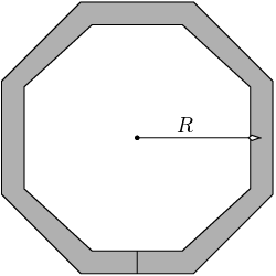
Practical inductors usually have the shape of regular polygons. For this case we approximate \(R\) as the distance of the center of the inductor to the middle of a polygon side (see Fig 2).
To obtain an estimate for the error introduced by the above geometrical approximations we compared the value predicted by the formulas (\ref{eq:ring-self-ind-exact}) and (\ref{eq:ring-self-ind-approx}) with the inductance computed numerically by a quasi-magnetostatic field solver called FastHenry [3]. The results obtained at 10 GHz for inductors made of copper and with \(T=1\) \(\mu\)m, \(R=50\) \(\mu\)m and having \(N_s\) sides, are shown in Tab 1. Note that at 10 GHz the skin depth in copper is \(0.66\) \(\mu\)m.
| Geometry | FastHenry | Eq. (\ref{eq:ring-self-ind-exact}) | Eq. (\ref{eq:ring-self-ind-approx}) | |||
|---|---|---|---|---|---|---|
| \(W\) | \(N_S\) | \(L\) | \(L\) | rel. err. | \(L\) | rel. err. |
| [\(\mu\)m] | [-] | [nH] | [nH] | [%] | [nH] | [%] |
| 1.00 | 32 | 0.2871 | 0.293 | 2.06 | 0.294 | 2.40 |
| 2.00 | 32 | 0.2616 | 0.266 | 1.68 | 0.269 | 2.83 |
| 4.00 | 32 | 0.2311 | 0.233 | 0.82 | 0.237 | 2.55 |
| 8.00 | 32 | 0.1963 | 0.194 | -1.17 | 0.2 | 1.88 |
| 1.00 | 8 | 0.2984 | 0.293 | -1.84 | 0.294 | -1.51 |
| 2.00 | 8 | 0.2720 | 0.266 | -2.24 | 0.269 | -1.14 |
| 4.00 | 8 | 0.2403 | 0.233 | -3.04 | 0.237 | -1.37 |
| 8.00 | 8 | 0.2044 | 0.194 | -5.09 | 0.2 | -2.15 |
| 16.00 | 8 | 0.1660 | 0.151 | -9.04 | 0.16 | -3.61 |
| 32.00 | 8 | 0.1268 | 0.104 | -17.98 | 0.118 | -6.94 |
4 Mutual Inductance
Similarly to the self-inductance, the mutual inductance \(M\) can also be defined in terms of the flux \(\Phi\): the mutual inductance between the current loop \(i\) and the current loop \(j\), where loop \(k=i,j\) is flown by a current \(I_k\), generates a magnetic induction \(B_k\) and spans a surface \(\Omega_k\) is \[\begin{equation} M_{ji} = \frac{\Phi_j}{I_i} \nonumber = \frac{1}{I_i} \int_{\Omega_j} \mathbf{B}_i\ \mathbf{\dd\omega}\ . \end{equation}\] Note that due to reciprocity \(M_{ij} = M_{ji}\).
4.1 Concentric Rings
The mutual inductance between the loop ring of radius \(R\) and a coplanar, concentric ring of radius \(\tilde{R} < R\) is \[\begin{equation} \label{eq:2conc-rings-exact} M_{cr} = 2\pi \tilde{R}\cdot\frac{\underline{A}_\phi(\tilde{R})}{\underline{I}_0}\ , \end{equation}\] where \(\underline{A}_\phi\) is the field generated by the loop ring of radius \(R\) given by Eq. (\ref{eq:ring-vector-potential-elliptic}).
As for the self-inductance, it is possible to obtain an approximate analytic expression with the help of the complete elliptic integral approximations (\ref{eq:elliptic_kc-epprox}) and (\ref{eq:elliptic_ec-epprox}). With these approximations, for \(0.5 \lesssim \tilde{R}/R < 1\) and with the following partial results \[\begin{align} m &= \frac{4\frac{\tilde{R}}{R}}{(1+ \frac{\tilde{R}}{R})^2} \\ 1 - m &= \frac{(1 - \frac{\tilde{R}}{R})^2}{(1+ \frac{\tilde{R}}{R})^2} \\ 2 - m &= 2\cdot \frac{1 + (\frac{\tilde{R}}{R})^2}{(1+ \frac{\tilde{R}}{R})^2}\ , \end{align}\] the mutual inductance is calculated to \[\begin{equation} \label{eq:2conc-rings-approx} M_{cr} \approx \mu R(1 + \frac{\tilde{R}}{R}) \left[ \frac{1 + (\frac{\tilde{R}}{R})^2}{(1+ \frac{\tilde{R}}{R})^2} \cdot \ln\left( 4\cdot\frac{1 + \frac{\tilde{R}}{R}}{1 - \frac{\tilde{R}}{R}}\right) - 1 \right] \ . \end{equation}\]
4.2 Non-Overlapping Coplanar Rings
The mutual inductance between two non-overlapping coplanar circular rings of radius \(R\) and \(R_2\) respectively, and with a center-to-center distance \(D\) can not be calculated analytically exactly. We can however give approximate expressions.
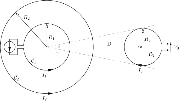
In a first approximation we use Eq. (\ref{eq:ring-vector-potential-elliptic}) to represent the field of the first loop and calculate the flux induced over a Kreisringsektor defined by the outer radius \(D+R_2\), the inner radius \(D-R_2\) and the aperture angle \(\gamma\): \[\begin{align} \label{eq:2rings-mutual-ring-sector} %\lefteqn{M_{dr} \approx} \\ M_{dr} &\approx -\frac{\gamma}{I_o}\left[ (D+R_2)\underline{A}_\phi(D+R_2) - (D-R_2)\underline{A}_\phi(D-R2) \right] \mathcal{Q} \\ \mathcal{Q} &= \frac{R_2^2 \pi}{\frac{\gamma}{2}[(D+R_2)^2 - (D-R_2)^2]} \ .\nonumber \\ \gamma &= 2\arctan(R_2/D) \nonumber \end{align}\] where the factor \(\mathcal{Q}\) is used to scale the Kreisringsector area so as to make it equal to the one of the ring.
In the second approximation valid for \(D\gg R, R_2\) we calculate the magnetic induction generated by the first loop ring at the center of the surface spanned by the second one with the help of Eq. (\ref{eq:circular-loop-far-magnetic-induction-general}). We also approximate the magnetic induction as being constant over the area of the second loop. Under these approximations the mutual inductance becomes \[\begin{equation} \label{eq:2rings-mutual-far} M_{g} = \frac{\mu}{4\pi} \frac{A_1 A_2}{D^3}\ , \end{equation}\] with \(A_i\) the area spanned by the current loop \(i\).
4.3 Comparison with Numerical Solution
In this section we estimate the error of the approximate formulas (\ref{eq:2rings-mutual-ring-sector}) and (\ref{eq:2rings-mutual-far}) for the mutual inductance between two non-overlapping coplanar rings by comparing the predicted value with the one calculated numerically by FastHenry. The numerical solution was calculated at 1 GHz for inductors made of copper and having a regular polygon shape with 32 sides and a square cross section of side \(1\) \(\mu\)m. To compute the values with the approximate formulas we used the same geometrical approximation as described in Sec. 3.1. The results of the comparison are shown in Tab. 2.
| FastHenry | Eq. (\ref{eq:2rings-mutual-ring-sector}) | Eq. (\ref{eq:2rings-mutual-far}) | ||||
|---|---|---|---|---|---|---|
| 2-7 \(D\) | \(L\) | \(M\) | \(M_{dr}\) | rel. err. | \(M_g\) | rel. err. |
| [\(\mu\)m] | [nH] | [pH] | [pH] | [%] | [pH] | [%] |
| 128 | 0.289 | 4.744138 | 4.693 | -1.08 | 2.941 | -38.01 |
| 256 | 0.289 | 0.406773 | 0.4 | -1.67 | 0.37 | -9.04 |
| 512 | 0.289 | 0.047660 | 0.047 | -1.38 | 0.046 | -3.48 |
| 1024 | 0.289 | 0.005856 | 0.0058 | -0.96 | 0.0057 | -2.66 |
| 2048 | 0.289 | 0.000728 | 0.00072 | -1.10 | 0.00072 | -1.10 |
5 Concentric Ring Shielding Effect
In this section we investigate the magnetic shielding effect provided by a metallic ring surrounding a spiral inductor. As is true for current microelectronic technologies, we assume that all inductors and loops are coplanar. Consider the following one of Maxwell’s equations \[\begin{equation} \label{eq:maxwell_div_b} \nabla\bullet\mathbf{B} = 0 \ . \end{equation}\] With the help of Gauss’s theorem we can put it in integral form \[\begin{equation} \label{eq:maxwell_div_b_int} \int_{\partial\Omega} \mathbf{B}\bullet\mathbf{d\omega} = 0 \end{equation}\] with \(\partial\Omega\) the surface of the volume \(\Omega\), and \(\mathbf{d\omega}\) an infinitesimal vector surface element. This equation states that the magnetic flux across the surface of any closed volume vanishes.
Lets chose as volume of integration the half sphere of radius \(R_s\) concentric with the shielding ring and cut on the plane defined by the ring. In section 2 we showed that at large distances from the ring the magnetic induction is perpendicular to the vector pointing from the center of the ring to the point of evaluation. In the limit \(R_s\to\infty\) the part of the integral (\ref{eq:maxwell_div_b_int}) not on the plane does therefore vanishes. We therefore conclude that the flux over the whole plane must be zero or, in other words, that the flux within the ring is equal and opposite in sign as the flux outside of the ring. With Faraday’s law we conclude that the ring will therefore oppose not only to changes in the flux in its interior, but also to any change in the flux in the whole plane outside of its area.
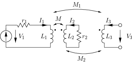
For a quantitative analysis consider the situation depicted in Figure 3 where ring \(\mathcal{C}_1\) is inside and concentric with a second closed ring \(\mathcal{C}_2\) and \(\mathcal{C}_3\) is a third open ring at a center-to-center distance \(D\) from the other two. Ring \(\mathcal{C}_1\) represents an inductor used in a large-signal circuit and should be isolated as best as possible from \(\mathcal{C}_3\) which represents the inductor used in a sensitive circuit. Ring \(\mathcal{C}_2\) should act as a magnetic shield an reduce the mutual coupling between \(\mathcal{C}_1\) and \(\mathcal{C}_3\). Note that, due to reciprocity, the roles of \(\mathcal{C}_1\) and \(\mathcal{C}_3\) can be exchanged.
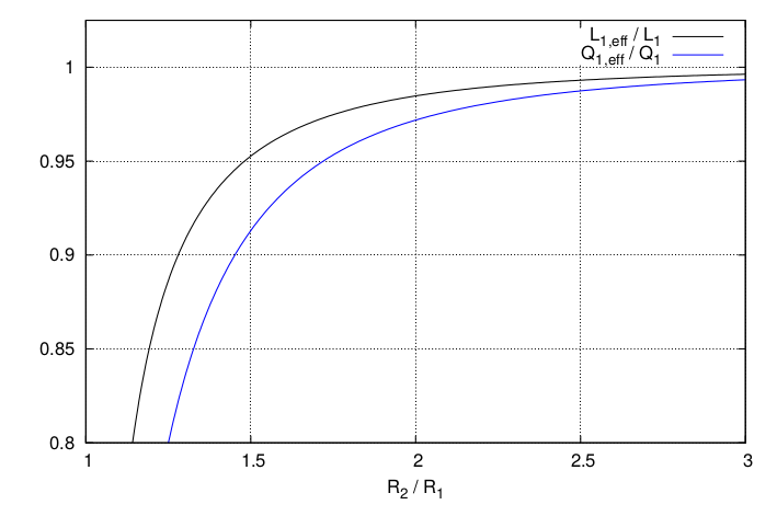
The electrical equivalent circuit of the system is shown in part (b) of the Figure and is described by the following equations \[\begin{align} V_1 &= (sL_1 + r_1) I_1 + sM I_2 \\ 0 &= (sL_2 + r_2) I_2 + sM I_1 \\ V_3 &= sM_1 I_1 + sM_2 I_2 \ . \end{align}\] With the help of the first two equations we can calculate the impedance as measured at the terminals of \(\mathcal{C}_1\). Assuming \(\omega L_2 \gg r_2\), with \(\omega\) the operating angular frequency, we obtain \[\begin{align} Z_1 &\approx \frac{V_1}{I_1} = sL_1(1 - k^2) + r_1 + r_2\left(\frac{M}{L_2}\right)^2\\ k &= \frac{M}{\sqrt{L_1 L_2}} \ . \end{align}\] From this equation we see that the effective self-inductance and the effective series resistance of \(\mathcal{C}_1\) are \[\begin{align} \label{eq:ring_w_shield_ind_eff} L_{1,\, \mathrm{eff}} &= L_1 (1 - k^2) \quad\mathrm{and}\\ \label{eq:ring_w_shield_ser_res_eff} r_{1,\, \mathrm{eff}} &= r_1 + r2 \left( \frac{M}{L_2} \right)^2 \end{align}\] respectively. The effect of \(\mathcal{C}_2\) on \(\mathcal{C}_1\) is therefore to reduce its self-inductance and to increase its losses.
To a good approximation, the series resistance \(r_i\) of loop \(\mathcal{C}_i\) is proportional to the loop radius \(R_i\). We can therefore estimate the effective quality factor of \(\mathcal{C}_1\) as \[\begin{align} \label{eq:ring_w_shield_q_eff} Q_{1,\, \mathrm{eff}} &= \frac{\omega L_1 (1 - k^2)} {r_1 + r2 \left( \frac{M}{L_2} \right)^2}\nonumber\\ &= \frac{\omega L_1}{r_1} \cdot \frac{(1 - k^2)} {1 + \frac{R_2}{R_1} \left( \frac{M}{L_2} \right)^2} \ . \end{align}\]
In a similar way as we did above for the self-inductance of \(\mathcal{C}_1\), we can calculate the effective mutual-inductance between \(\mathcal{C}_1\) and \(\mathcal{C}_3\) and obtain \[\begin{equation} \label{eq:ring_w_shield_m_coupl_eff} M_{1,\, \mathrm{eff}} = M_1 \left(1 - \frac{M_2 M}{M_1 L_2}\right) \ . \end{equation}\]
Accurate approximate formulas for all of the self- and mutual-inductances occurring in these expressions have been derived in the previous sections. We are therefore able to evaluate numerically the effect of ring \(\mathcal{C}_2\) on the self-inductance and quality factor of \(\mathcal{C}_1\) and on the mutual-inductance between \(\mathcal{C}_1\) and \(\mathcal{C}_3\). Note that for all three quantities the effect of the shield \(\mathcal{C}_2\) can be represented by a multiplicative factor which does only depend on ratios between distances. Part (a) of Figure 4 shows the normalized effective self-inductance and quality factor as a function of \(R_2/R_1\). Part (b) of the Figure shows the mutual-inductance values as a function of \(R_2/R_1\) for the case where \(R_1=R_3\), for various values of \(D/R_1\). The curves have been computed with Eqns. (\ref{eq:ring-self-ind-exact}), (\ref{eq:2conc-rings-exact}) and (\ref{eq:2rings-mutual-ring-sector}). For comparison we also show discrete points calculated with FastHenry at 1 GHz for \(N_s=32\), \(T=W=1\) \(\mu\)m and a conductivity 20 times larger than that of copper. The squares represent the results obtained for \(D/R_1=4\), while the circles the ones obtained for \(D/R_1=16\).
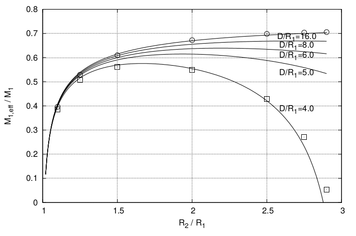
The curves show that a good shielding effect can only be obtained for two cases:
The first chase is where \(R_2/R_1\) is close to 1. In this case however, the shield has a strong undesired impact on the self-inductance of \(\mathcal{C}_1\) as well.
The second case is where \(R_2/(D-R_3)\) is close to 1. The large dimension of the shield makes this case impractical apart for inductors very close to each other.
In all other cases the shielding effect is quite moderate.
The small cross-section used in the numerical calculations was chosen to approximate as best as possible the ideal case studied analytically. The large conductivity was chosen to guarantee \(\omega L_2 \gg r_2\) in spite of the small cross section. For the case of practical inductors made with wide metal strips, the shielding effect improves slightly.
6 Multi-Turn Loops
In the case of spiral inductors with more than one turn, the self- and mutual-inductances can all be calculated by combining the formulas given in the preceding sections. The resulting formulas are however quite complex and they do not provide much insight. Instead of accurate but complex expressions, in this section we use first-order approximations to extend the investigations presented in Sec. 5 to the case of multi-turn spiral inductors. To do this, we assume that all turns of a multi-turn spiral inductor have the same size1.
With the above simplifying assumption, the self-inductance of a spiral inductor with \(N\) turns can be estimated from the formula for the single-turn one by noting that the various turns are connected in series with each other and that each turn is crossed by the same flux. In addition, each turn carries the same current. The magnetic induction and therefore the flux crossing each turn is therefore \(N\) times larger than in the single-turn case. The ratio of the self-inductance of a spiral-inductor with \(N\) turns to the one of a single turn inductor is therefore \[\begin{equation} \label{eq:self_ind_multi_turn_to_single} \frac{L_{TN}}{L_{T1}} = N^2 \ . \end{equation}\]
From similar considerations, the ratio of the mutual-inductance between an inductor \(i\) with \(N_i\) turns and a second inductor \(j\) with \(N_j\) turns to the one between two single turn inductors is \[\begin{equation} \label{eq:mutual_ind_multi_turn_to_single} \frac{M_{TN}^{ij}}{M_{T1}^{ij}} = N_i N_j \ . \end{equation}\]
With (\ref{eq:self_ind_multi_turn_to_single}) and (\ref{eq:mutual_ind_multi_turn_to_single}) we can now extend the problem shown in Fig. 3 and assume that \(\mathcal{C}_i\) has \(N_i\) turns, with \(i=1, 2, 3\). We find that the effective self-inductance and the effective mutual-inductance over the respective value with no magnetic shield \(\mathcal{C}_2\) is unaffected.
7 Conclusions
In this study the magnetic properties of circular metallic rings as typically used to implement spiral inductors on integrated circuits were investigated. Expressions for the electromagnetic fields were derived from the general solution of Maxwell’s equations. Both, the far-fields responsible for radiation, as well as the fields in the quasi-static approximation were calculated. The latter are the dominant components determining the couplings between different inductors on the same IC at RF frequencies.
Based on the calculated fields, the self-inductance of circular spiral inductors with a circular cross-section was determined and the change in self-inductance when a rectangular cross-section is used instead was investigated numerically. It was found that, by suitably choosing effective radii, the formula is accurate to better than 10 % for a width to thickness ratio in excess of 16.
The important topic of coupling was addressed next. Approximate expressions for the mutual inductance between two distant coplanar circular inductors as well as for concentric-coplanar inductors were derived. The accuracy of the expressions was investigated numerically and was found to be remarkably accurate (less than 2 %) even for the case where the distance between the inductors is small.
The effect on self- and mutual-inductance between two distant coplanar inductors when one of the two inductors is surrounded by a third concentric ring was then analyzed quantitatively. It was found that, for a negligible effect on the self-inductance, the mutual inductance can be decreased by approximately 6 dB. A larger coupling reduction can be achieved by either making the third ring very large, or by accepting a reduction of both, self-inductance and quality factor of the surrounded inductor.
8 Appendix
Complete Elliptic Integrals
The complete elliptic integral of the first kind \(K(m)\) is defined as \[\begin{aligned} \label{eq:elliptic_kc} K(m) = \int_0^{\pi/2} \frac{1}{\sqrt{1 - m\sin^2\theta}}\ \dd\theta\ . \end{aligned}\] The one of the second kind \(E(m)\) as \[\begin{aligned} \label{eq:elliptic_ec} E(m) = \int_0^{\pi/2} \sqrt{1 - m\sin^2\theta}\ \dd\theta\ . \end{aligned}\] \(m\) is called the elliptic integral parameter.
Coplanar Rings Self- and Mutual-Inductance Computation Tool
The following form computes the self- and mutual-inductances for the planar geometric situation depicted in Fig. 3. The values are computed based on Eqns. (\ref{eq:ring-self-ind-exact}), (\ref{eq:2conc-rings-exact}) and (\ref{eq:2rings-mutual-ring-sector}). The elliptic integrals are calculated with the help of the polynomial approximations given in [2].
| Quantity | Value | Unit |
|---|---|---|
| \(\mu\)m | ||
| \(\mu\)m | ||
| \(\mu\)m | ||
| \(\mu\)m | ||
| \(\mu\)m | ||
| nH | ||
| nH | ||
| nH | ||
| pH | ||
| pH | ||
| pH | ||
| — | ||
| — | ||
| — |
Magnetic Dipole Radiation Resistance Computation Tool
| Quantity | Value | Unit |
|---|---|---|
| \(\mu\)m | ||
| GHz | ||
| \(\Omega\) |
References
We do not make use of Wheeler’s empirical formula [4] for the self-inductance of multi-turn inductors because of the desire to treat the mutual-inductances on the same footing as the self-inductances and, to the authors knowledge, the lack of similar formulas for the mutual-inductances.↩︎
